Automatic Flow Control Valve Symbol

The Most Common Control Valve Symbols On A P Id Kimray Blog
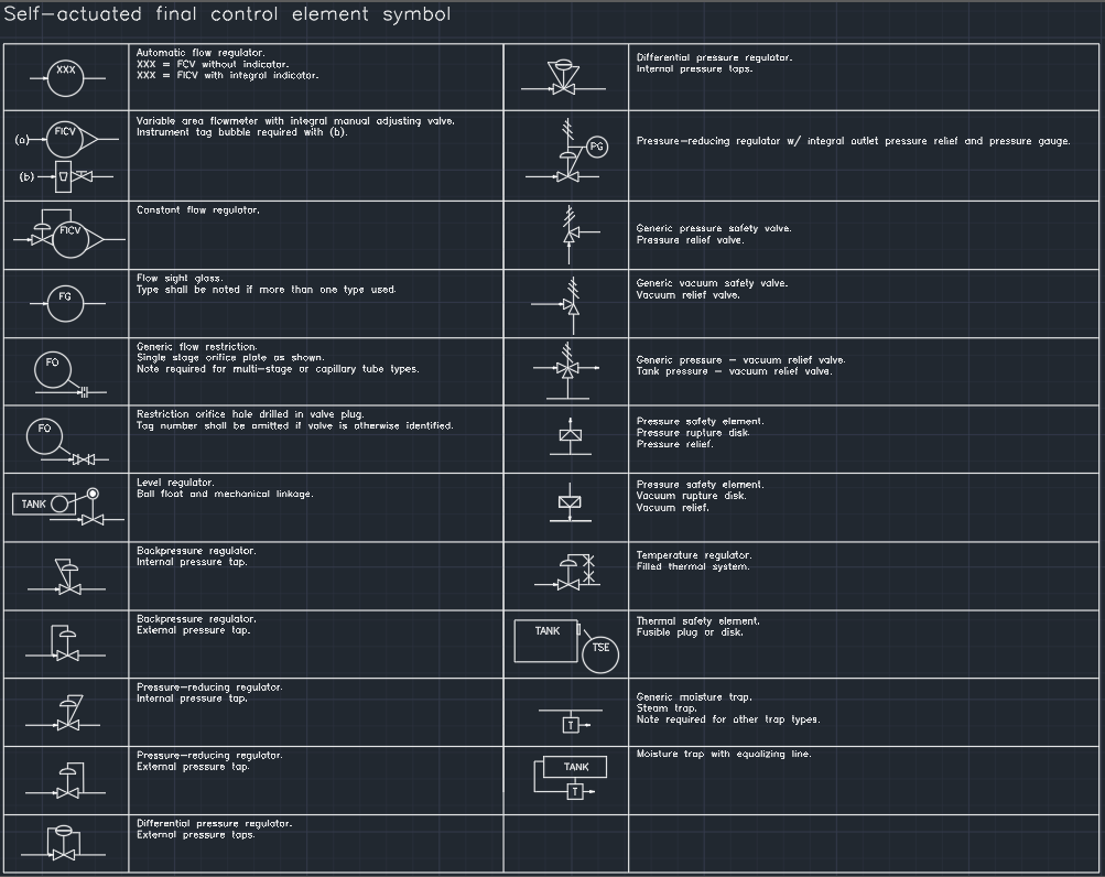
Self Actuated Final Control Element Symbol Cad Block And Typical Drawing

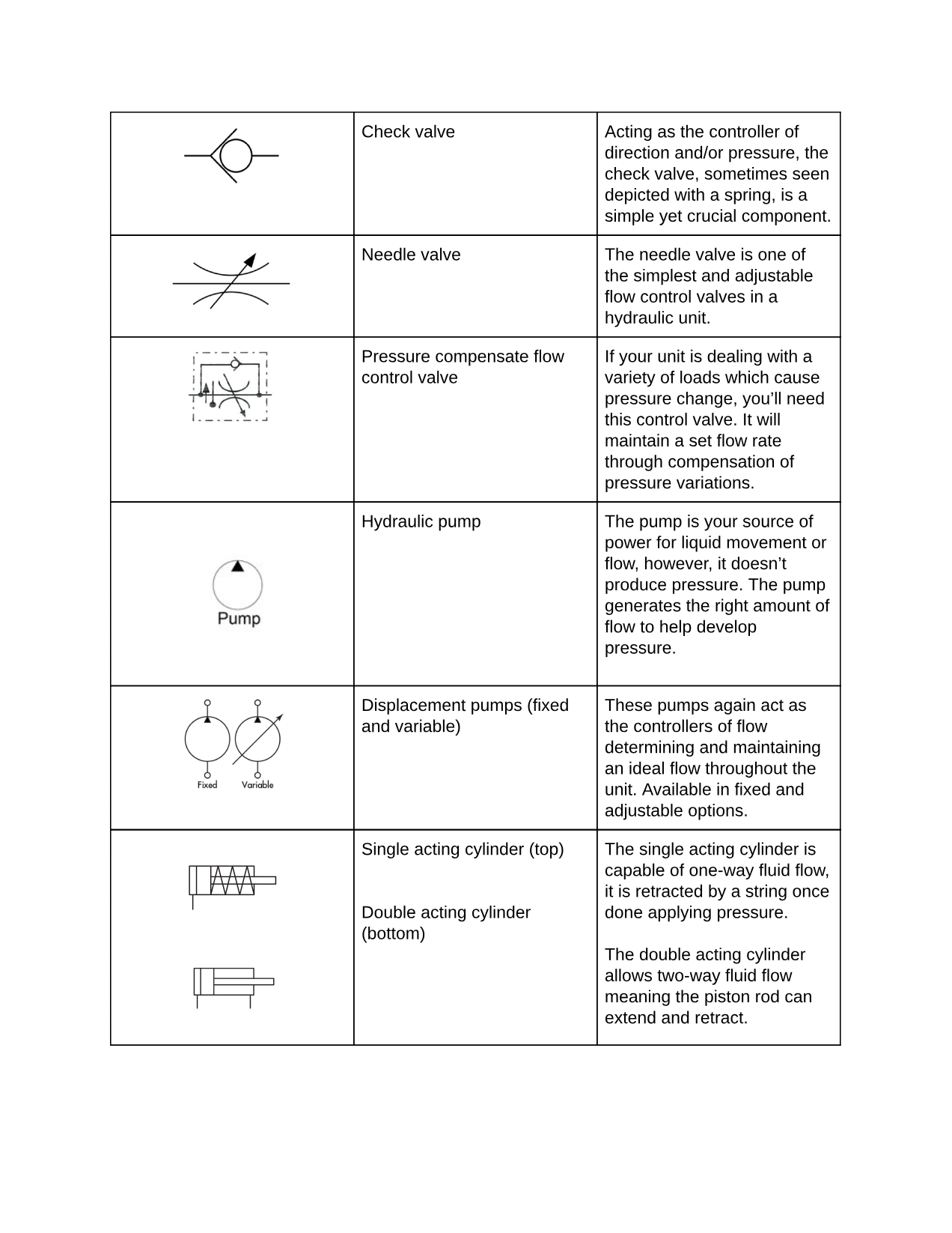
Reading Fluids Circuit Diagrams Hydraulic Pneumatic Symbols
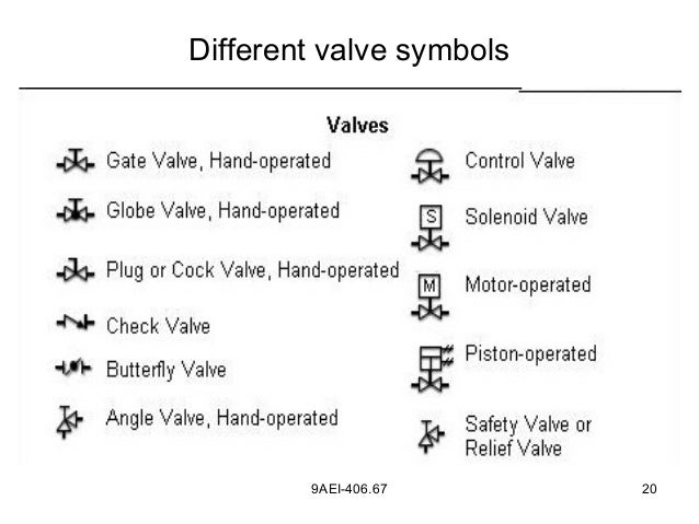
Solenoid Valve Symbols
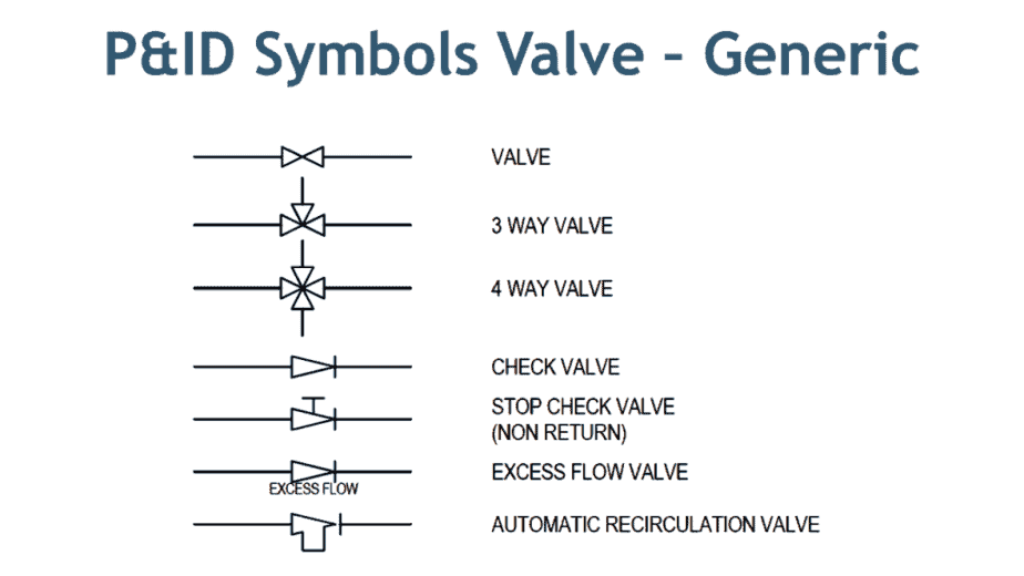
Valve Symbols In P Id Ball Valve Relief Valve And More
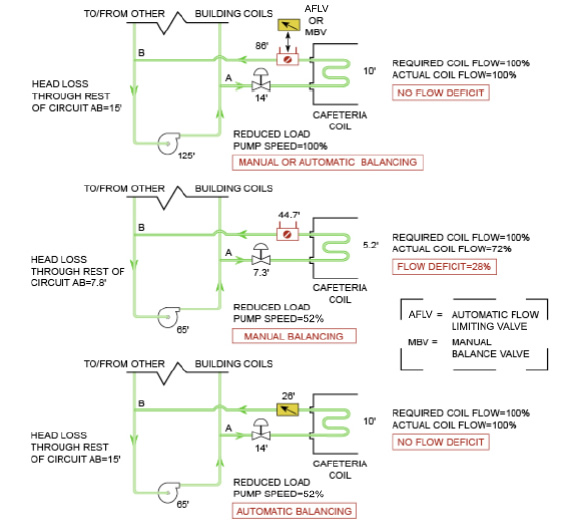
Manual Valves Vs Automatic Flow Limiting Valves Griswold Controls

For a demonstration of the flow control valve in action click here.
Automatic flow control valve symbol.

How To Create P Id Drawings Inside Autocad

Modeling A Flow Control Valve Engineered Software Knowledge Base

P Ids Piping Instrumentation Diagrams And P Id Valve Symbol Library Assured Automation
Http Superiorrex Com File 11474 Rahc 2007 25 18
Process Control 5 Chapter
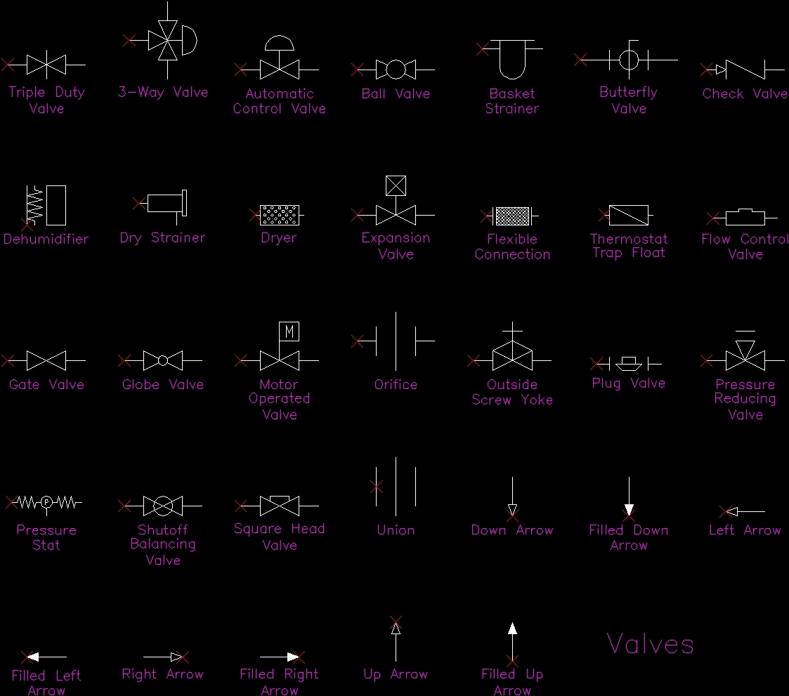
Hidraulic Symbols Dwg Block For Autocad Designs Cad
Https Sites Ntc Doe Gov Partners Tr Training 20textbooks 08 Engineering 20symbology 20prints 20and 20drawings 2 Mod 202 Engineering 20fluid 20diagrams 20and 20prints Pdf

Chapter 2 Process Selection Engineering360

P Id Symbols For Control Valve Assmbly And Actuators Enggcyclopedia
Http Recursosbiblio Url Edu Gt Publicjlg Lib 2015 05 Manutec Ind Draulic Tec 16 Ap A Pdf
How To Read A Schematic Understanding Of Graphical Symbols Used In Fluid Power Drawings Air Hydraulic Equipment Inc

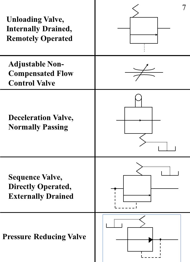
Hydraulic Symbology 201 Industrial Directional Valves

Function Symbols Learn Automation Electrical And Instrumentation
Https Www A1es In Downloads A1es Pipe And Identification Diagrams Pdf
Fluid Power Symbols Ppt Download
Https Www Cedengineering Com Userfiles Control 20valves 20basics 20 20sizing 20 20selection Pdf

Valve Symbols Weight Loaded Actuating Method Wedge Gate Valve Wedge Valve Valve Statically Loaded Actuating Method Spring Valve Design Elements Symbols
Http Www Deicontrols Com Wp Content Uploads 2018 01 Pressure Indepement Control Valves Pdf
Https Encrypted Tbn0 Gstatic Com Images Q Tbn 3aand9gcrjc2srkq8adx Appabvxuyjog9bvy0ghxsswvyri2p D5gicsu Usqp Cau

Design Elements Valves Design Elements Valves And Fittings Retract Resistor Check Valve Application Check Valve Symbol Flow Direction
Camozzi Valves Technical Information Hi Tech Controls
Industrial Process Control Standards Ppt Video Online Download

Interior Design Piping Plan Design Elements Mechanical Drawing Software Retract Resistor Check Valve Application Valve Drawing Software

Automatic Control Valves Automatic Controlling Valves Latest Price Manufacturers Suppliers
Source : pinterest.com
